Mechatronics
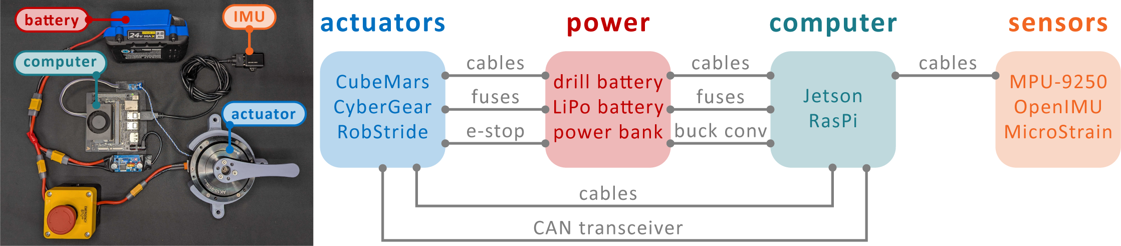
The mechatronic system to run actuators with your computer can be broken down into three main components:
Computer: Jetson (which requires 19V/1-3.5A) or Raspberry Pi (5V)
Actuator: CubeMars AK-series actuator (~24V-48V), CyberGear Micromotor (~24V), or RobStride actuator (~24V)
Batteries: Either a uniform power source (powers both computer and actuators) or two separate power sources
Power System
What you will need:
12 gauge black and red wire, depending on actuator
XT30 (or XT30 (2+2)) connectors
Emergency stop
Fuse holder
Fuse (20A)
Buck converter (if using unified power for computer and actuators)
Power bank connection cable (if using separate power for computer)
Battery mount (if using drill battery)
Tip
We recommend adding XT30 male/female connections in your wiring setup to enable easy removal/replacement of any sections of the power setup that you may want to be modular or easily replaceable.
Power - Battery Connections
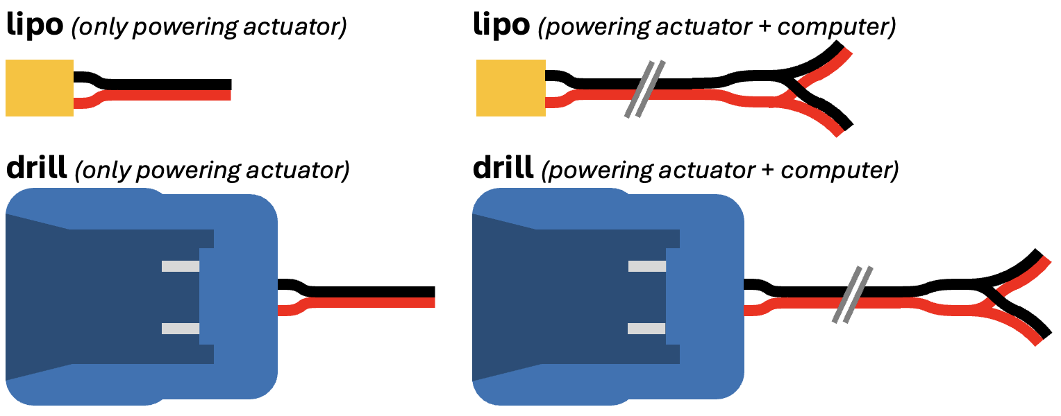
In the diagram below, we show 4 possible setups. The only differences in these configurations is which battery you’re using (lipo vs. drill) and if you’re using unified or separate power for your computer.
If you’re using a…
Lipo battery: Solder black/red wire onto a female XT60 connector
Drill battery: Solder black/red wire onto the corresponding black/red wire protruding from the battery adapter
You will need:
Drill battery mount OR XT60 female connector
Power - Actuator Connections
Tip
If you order the recommended fuse holders from our Ordering Guide, we recommend trimming the included red wire because it is significantly less flexible than the generic 12-gauge red/black wire.
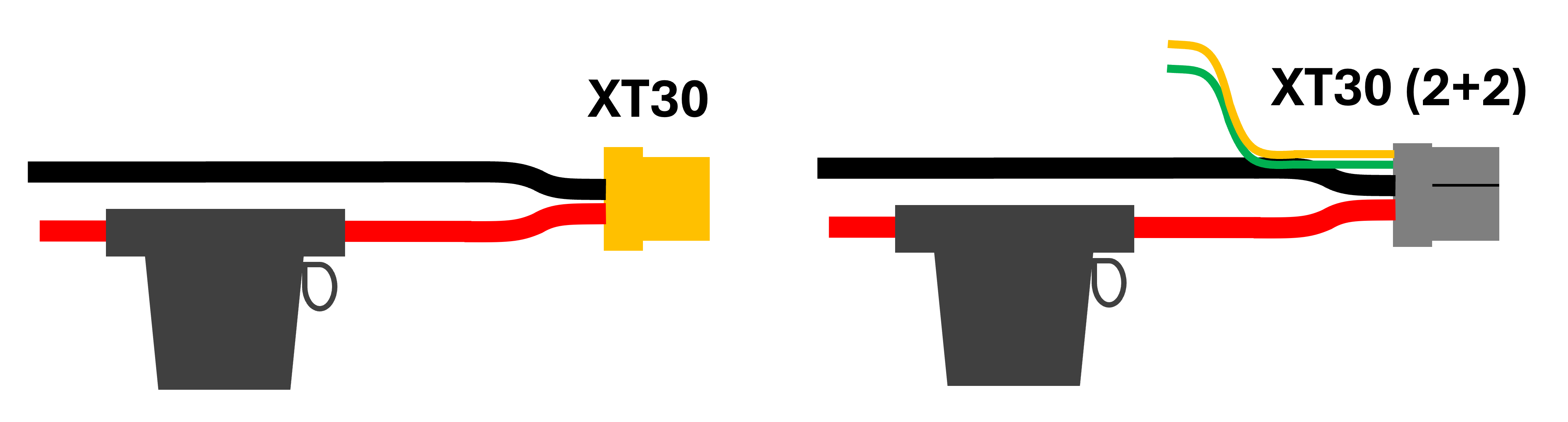
XT30 connector options
First, you will need to check which XT30 connector your actuator uses. For older models of the CubeMars AK-Series, this is a standard XT30 connector. However, the V3 devices along with the RobStride and CyberGear devices use an XT30 2+2 design, where the CAN bus wiring is directly integrated with the power connector. For the rest of the diagrams, the standard XT30 connector is shown. However, you will need to connect the high and low can connector into the appropriate pins on the XT30 (2+2) if your actuator requires it.
You will need:
12 gauge black and red wire
Emergency stop
Fuse holders and fuses (number needed = number of actuators)
XT30 or XT30 (2+2) male connectors (number needed = number of actuators)
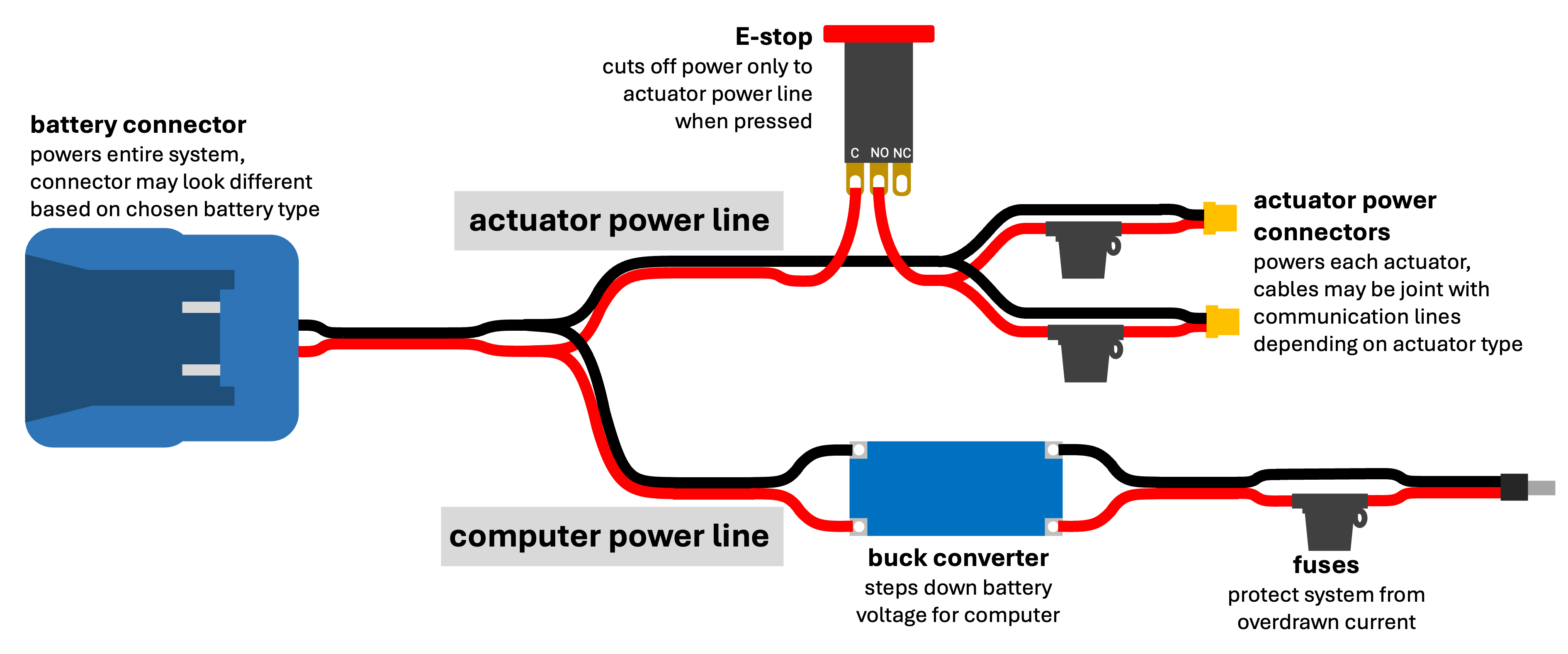
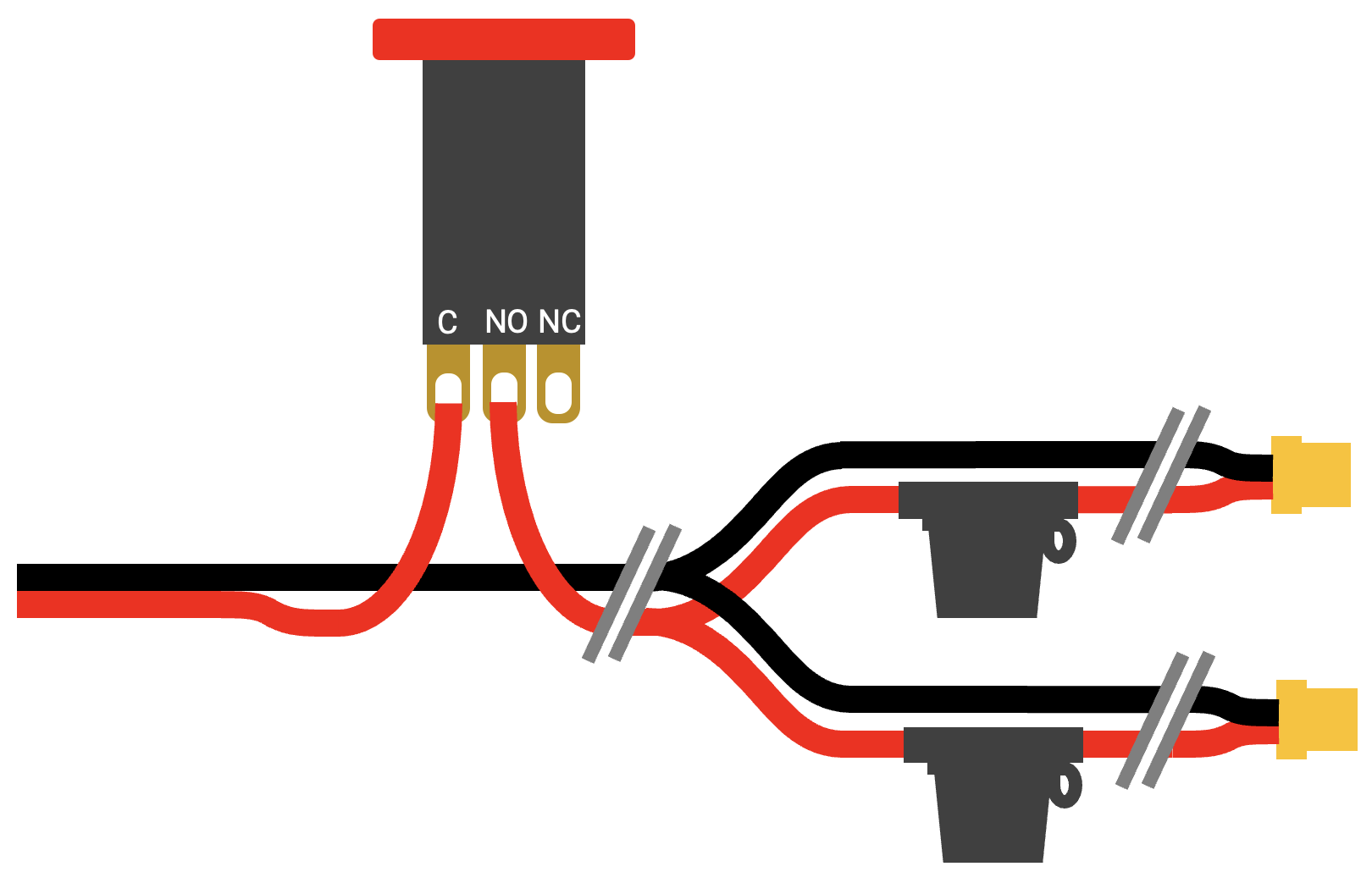
The emergency stop should be before you split the power connectors in parallel to the actuators, and the fuses should be after the split. This way, the emergency stop can stop both actuators and the fuses only limit the per-actuator current.
Tip
In a few cases in our lab, a suboptimal fit between the XT30 male connector and actuator has resulted in the cable slowly loosening over the course of the experiment. To prevent this, we recommend orienting your actuator so that the power cable enters from the top (and thus gravity will not loosen it over time).
Power - Computer Connections

You will need:
12 gauge black and red wire
Buck converter (if using higher voltage source)
Fuse holder and fuse
Computer power cable (barrel jack, micro-USB, OR USB-C)
Depending on your choice of computer, you will need to set the output voltage of your buck converter accordingly. Our recommended buck converter in the Ordering Guide allows you to adjust the output using a Phillips head screwdriver. Connect the input side to your battery and the output side to a multimeter measuring DC voltage, then adjust the potentiometer on the buck converter with a screwdriver until the output voltage matches your computer’s input (Jetson - 19V, Raspberry Pi - 5V).
Important
Adjust voltage output before connecting your computer to avoid any risk of overvolting.
Also note that standard buck converters are unidirectional, so if using unified power for computer and actuators, ensure the battery is connected to the input side and the computer is connected to the output.
Actuator Communication System
Both the Jetson and Raspberry Pi configurations require an additional device to be connected to the system, which outputs the appropriate CAN High and Low signals.
Jetson
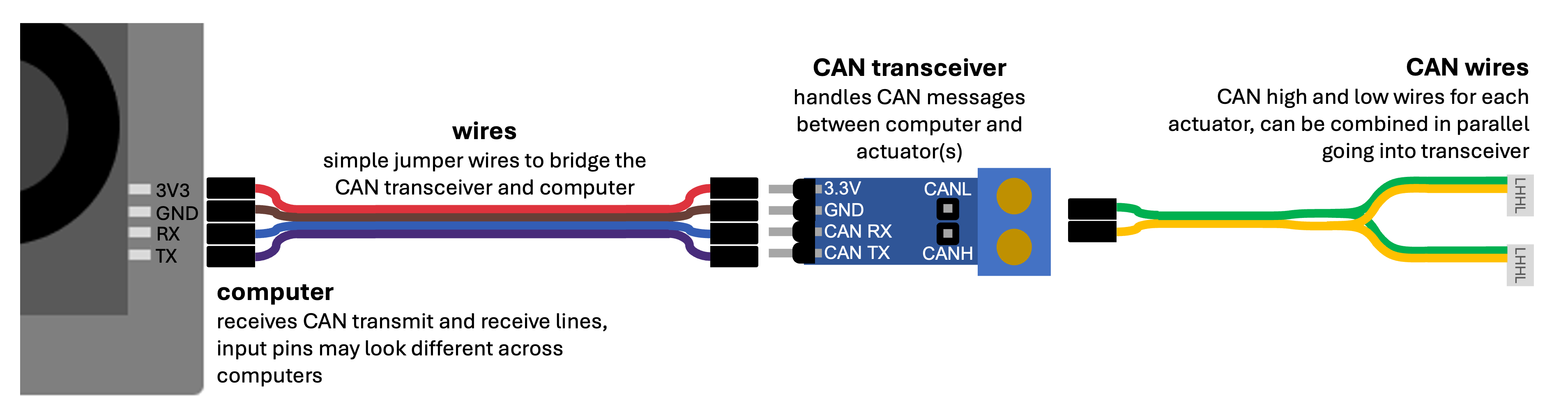
On the Jetson, a CAN transceiver is needed, and is wired into the CAN RX, and CAN TX pins as shown below.
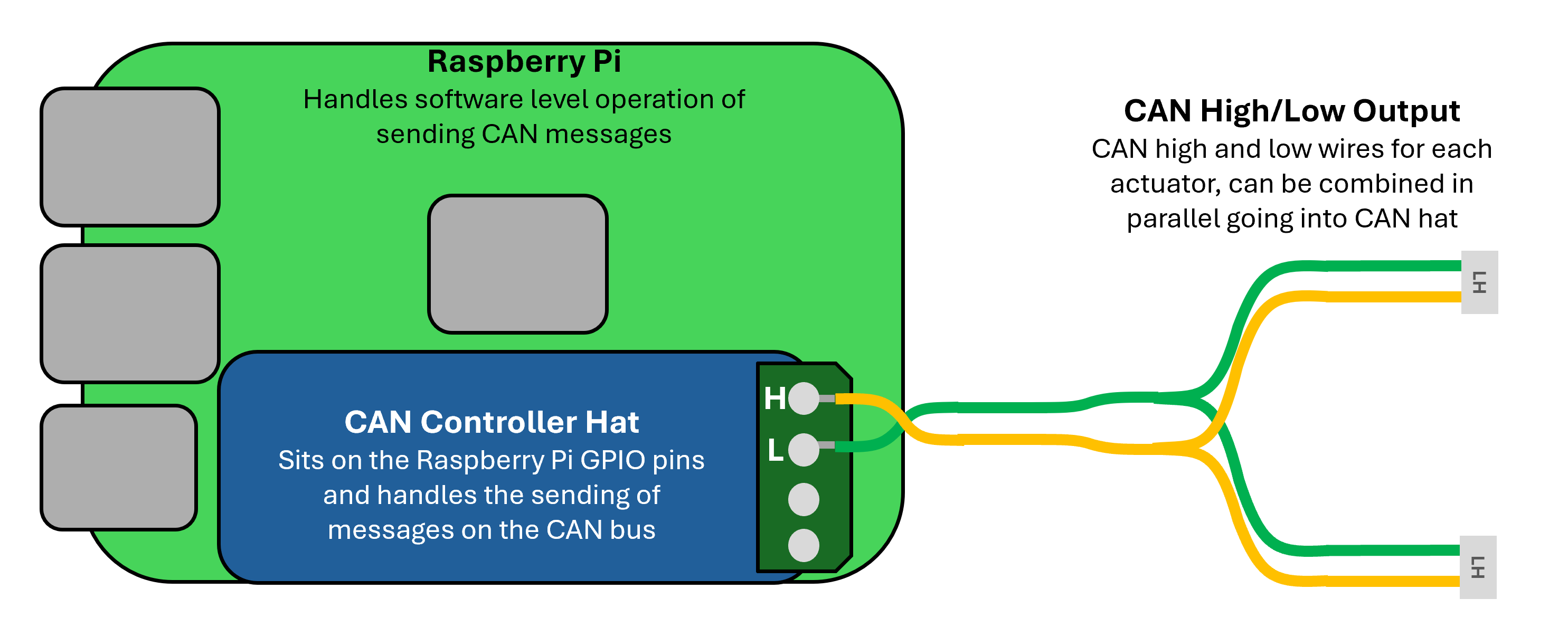
Raspberry Pi
On the Raspberry Pi, a CAN controller hat is needed, which plugs into the GPIO header pins on the Raspberry Pi as shown below.